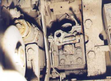
Picture 26
You've switched to the loader's position and you're looking straight forward. Your coaxial MG 34 would normally be mounted in the contraption shown in the middle of the photograph. The main gun's breech is to your left. You can see the upper left corner of the vision block bin at the photograph's right edge.
|
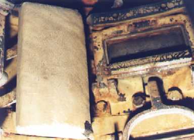
Picture 27
This is the inside of the commander's cupola. One of the cupola's five windows can be seen in the upper right. For protection this was made with a thick laminated block of glass. Each window featured its own armored visor and the lever shown in the lower right corner of the picture is used to open and close this visor.
|
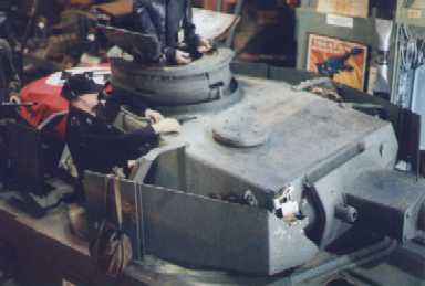
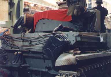
Picture 28
Here we have a good view of the turret's roof, including the cupola, armored fume extractor vent, the doubled door commander's hatch, and the Syrian-added anti-aircraft gun mounting around the top of the cupola. Two of the cupolas's five view ports can be seen here as well.
|
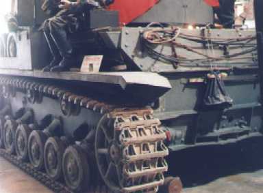
Picture 29
This shot includes a fairly good look at the Ausf. H late model track links. As you might expect, the unique pattern on the running surface has long since been warn away.
The omission of spare track links in the upper left of the hull rear also indicates a late production Ausf. H. On earlier models, the left "hook" for the tow cables was moved over to the right to accomodate these spare links.
The mufflers are missing -- the auxiliary engine's little squarish muffler would normally appear in the middle on the far left and the primary engine's large cylindrical muffler would be mounted to the right of that.
You can see where the starter crank is inserted just left of the lower section's center. The track tensioning units are located to the extreme left and right of this lower section.
|
Picture 30
Now we get a better look at where the main muffler connects (the extreme right side of the middle section). In the center of this same area you see the cooling water drain sticking out from under the missing muffler. The cooling water exchange port is lurking in the shadows just below and to the left of the drain.
|
|
Previous Page |
1 |
2 |
3 |
4 |
5 |
6 |
Next Page
|