Picture 6
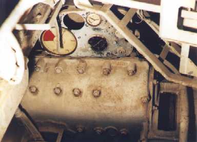
You're now looking to your right. This shot shows the main control panel and the transmission housing below it.
The transmission on the Ausf. H and Ausf. J was the Synchron ZF SSG 77.
If you look closely you will see that the control panel has a small plaque mounted at the bottom middle. This has been painted over, but normally shows the pattern for shifting between the tank's 7 gears -- 6 forward and 1 reverse.
|
Picture 7
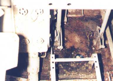
This shows the floor area in front of where the driver sits. At the bottom of the photo you see the seat less the cushions. In the upper left is the housing of the left steering brake.
|
Picture 8
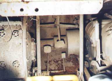
On your left is the steering brake housing. The transmission and shifting lever are on the extreme right.
The two levers to your immediate left and right give you control over the Wilson-Krupp clutch and brake system used for steering.
|
|
|
|
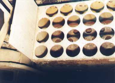
Picture 9
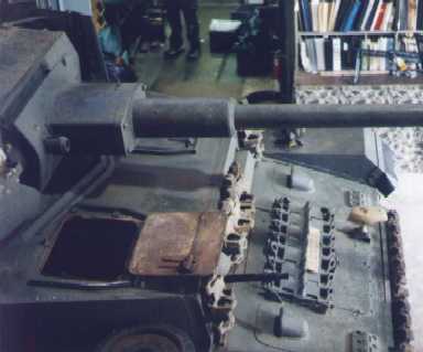
Here's another view of the sheet metal stowage bin located behind the driver. It's designed for the 75 mm. ammunition used in the main gun.
In the case of this particular bin, the rounds are stored nose down. For each large round opening on the top of the bin there is a corresponding smaller hole directly below it. The tapered nose of the round rests in the smaller hole while the larger one holds it upright.
Unlike later models, such as the one pictured here, the Ausf A's bin had at least three of its sides extended approx. 3 inches beyond the top/horizontal sheet (the side nearest the gunner may have stopped flush with top sheet). Also, the top sheet was stamped so that each opening had a neat little flange that sweeps upward. In the photos I've seen it almost looks as if later models used this same top sheet but flipped over so that the flanges sweep downward. And, finally, the rows nearest the driver each held 7 rounds instead of 6 (and the rearmost row presumably held 6 instead of the newer bins' 5).
The bin pictured here is basically the same as those used on models dating back to Ausf. G or earlier (probably back to the F2).
|
Picture 10
This photo gives us a look at the interior of the radio operator's hatch -- note the latch that locks the door shut. The 5-sided design of the splash guard around this hatch indicates that this hull is an early Ausf. H as the later model featured a simplified square 3-sided design. It's interesting, however, that the location of the loop for the pad-lock (the tiny protrusion just behind the hatch opening) indicates a late model Ausf. H. This isn't surprising since little changes like these were casually made mid-stream during a given production run. So perhaps our hull here is a "mid" production Ausf. H.
The splash guard in front of the turret has the blunted V shape of the early Ausf. style. From late Ausf. H onward the lower bevel is pointed just like the upper bevel.
|
|
Previous Page |
1 |
2 |
3 |
4 |
5 |
6 |
Next Page
|