|
|
AAF's Ausf. H/J Inside & Out
Picture 11
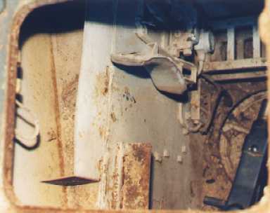
Here we're looking down through the radio operator's hatch. In the lower right corner of the picture you see the breech of the bow machine gun.
|
Picture 12
Now you're sitting in the radio operator's position. In front of you is your 7.92 mm. MG 34 machinegun. This is basically the same well-liked machinegun used in the field by the infantry and it continued to be used as the standard German tank machine gun throughout the war.
|
|
|
|
Picture 13
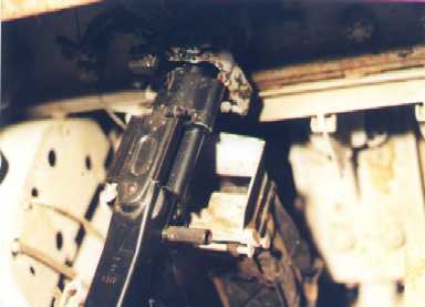
Here's another view of the hull machinegun. In the background below the machine gun you can see the right steering brake housing and to the left is the transmission. At top left is one of the radio receivers.
In this photo we can clearly see the folding travel lock -- the hinged triangular piece hanging down from above the gun. When attached, this device kept the gun from swinging around while the vehicle was on the move.
Down and left of the travel lock is an armature to which a large spring was originally attached. This spring ran from the end of the armature to the ceiling above and was designed to help counter the breech-heavy mounting. The original spring is long gone and appears to have been replaced by a piece of wire or string.
If you look closely just to the left of the rear-most part of the breech you will see an empty fitting. This fitting is tightened with a nut similar to the one visible to its immediate left. At one time an L-shaped bracket was mounted here. This bracket held a headpiece shaped like an inverted saucer. This was used in conjunction with the spring to balance and steady the gun while it was being fired. Also mounted to this same fitting was a "forehead cushion" for want of a better term. This was used to steady the gunner while using the sight (which is also missing here).
|
|
|
|
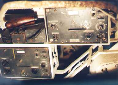
Picture 14
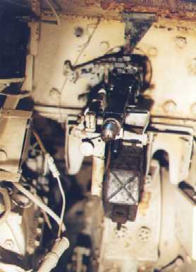
The radio operator's seat is located to the right of the driver with the transmission, control panel, and radios between them. To your left you see two Ukw.E.e. ultra short wave receivers. The rear of the driver's control panel can be seen in the lower right corner of the picture.
A regular non-command tank might ordinarily be equipped an Fu. 5 set only (which includes one Ukw.E.e receiver and one 10 W.S.c. 10 watt transmitter). A second Ukw.E.e receiver (designated as an Fu. 2 set) was often included in addition to the Fu. 5, especially in a command and control tank, such as that of the platoon leader. In the case of our tank here, the transmitter is missing. It was normally located on the right with the receivers on the left.
In the empty rack we see the telegraph key and, I assume, the stock from the MG 34 mounted by the museum in the hull. I'm not sure about the little box to the immediate right of the telegraph key. The photos I've seen of other types of German tanks show the telegraph key on a special little shelf for comfortable access. I wonder where it would be located in a PzKpfw. IV...
The radios slid into their respective racks and were then clamped securely into place. One of these clamps can be seen to the right of the lower receiver.
Both receiver and transmitter came with protective sheet metal covers that could be put into place when a radio was not in use.
The dial on the far left of each unit is marked "Feineinstellung" (fine tuning). This is used to calibrate to a standard setting of 30 megacycles.
Below the fine tuning dial are two receptacles for "fernhorner" (headsets). A "bordsprechkasten" (on-board speech box) was generally plugged in here. The driver's and radio operator's actual headsets would then be plugged in to this box along with the "turmanschluß" box (literally "tower link"). This second box is what the commander and gunner use with their headsets.
I assume that the meter at top center displays the current frequency setting.
The dial marked "Frequenz-Einstellung" (tuning control) is used to tune to the desired frequency.
The switch marked "Fern" (far) and "Nah" (near) is normally used in the "far" position. Moving it to the near position reduces the coupling to the receiver antenna input circuits when operating in a strong RF field. In practical terms, I believe, this means that you use the "far" setting when you're far away from the vehicle with which you are in communication and the "near" setting when you're close.
The receptacles to the right of this switch are marked "G. Ant." (counterpoise antenna) and "z.Sender" (to transmitter). Cables run from these to corresponding jacks on the transmitter marked "Ant. Empf. G." (antenna receiver counterpoise) on the transmitter.
Under these you find a dial labeled "Aus Ein Lautstarke" (off on volume). This is, of course, the on/off function combined with the volume control.
Finally, in the lower right corner we find the socket for the cable that connects the receiver to its power source, an E.U.a2 "umformer" (transformer, otherwise known as the "dynamotor"). The transformer gets its power directly for the tank's "sammler" (battery).
Due to variations in manufacturing it's possible that the dials seen here are all original. Based on other photographs I've seen, however, it appears that only the tuning controls and the lower unit's off-on-volume control are original.
|
Picture 15
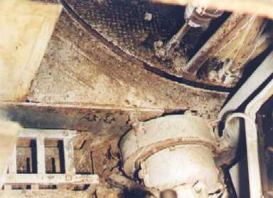
Now you're looking backwards and down from the radio operator's position. Here we can see the floor of the fighting compartment. A bit of the lower receiver can be seen in the lower right corner of the photo. The large round object is part of the transmission housing.
|
|
Previous Page |
1 |
2 |
3 |
4 |
5 |
6 |
Next Page
|
|