|
|
Technical Manual D 653/21a
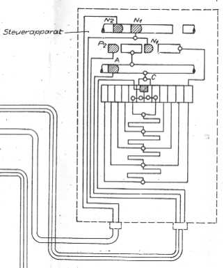
Picture 6
"Steuerapparat" translates to "Control Apparatus". This looks like it might be a control to adjust the speed of the turret's traverse.
|
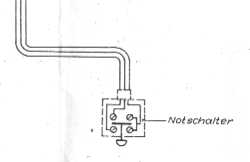
Picture 7
Emergency switches.
|
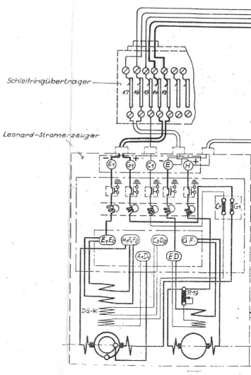
Picture 8
The unit at top, labeled "Schleifringübertrager" contains the slipring transducers.
The bottom unit represents the generator.
|
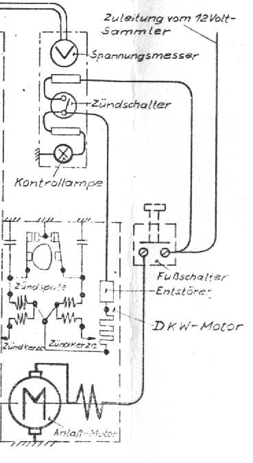
Picture 9
The top unit probably represents devices located at or near the driver's control panel. The circular symbol with the "V" inside represents a volt meter. The switch symbol labeled "Zündschalter" is the ignition switch. The bottom symbol, labeled "Kontrollampe", represents a light that turns on when the ignition switch is closed.
The unit to the lower left represents the auxiliary motor that supplies power to the generator. Translations: "Zündspule" = ignition coil, "Zündkerze" = spark plug, "Entstörer" = dejammer (a filter to minimize motor's interferance with radio signals), and "Anlaß-Motor" = engine starter.
The little unit to the lower right represents a foot switch. The line leading into this switch represents incoming power from the 12 volt batteries.
|
|
Previous Page |
Next Page
|
|