|
|
Inside Munster's Ausf. G
Manufacture of this tank was completed by Vomag in September, 1942BW-p184 STT15-p1. It was shipped to Tobruk where it joined Panzer Regiment 8 on October 21 of the same year. It was put into action on the front line on November 1 and captured sometime later in 1942.PGT1-p56
Its inspection by Britain's School of Tank Technology wasn't completed until August, 1943. It's likely that the difficulty of transporting captured equipment from Egypt, through or around enemy infested seas, is partly responsible for this delay. The examination took place at Chobham and was conducted by Major J. D. Barnes, RTR, Major W. de L. M. Messenger, RTR, and Captain N. F. Brand, EME. At the time of its inspection, its odometer indicated a mere 482 kilometers.STT15-p1
The hull, chassis number 83072STT15-p1, is clearly that of early Ausf. G production. This is evident by both the chassis number and by its features. It has the two holes made to accommodate the driver's episcope. The episcope itself was present when inspected by the School of Tank TechnologySTT15-p9. An early "double bar" spare track bracket is used on the bow and the spare road wheel storage is of the standard box type with no lock bar. The bracket for mounting 7 track links to the glacis plate, introduced in June, 1942TRACT4-p44, is present. The auxiliary motor used for turret traverse was present when the tank was initially examined by the School of Tank TechnologySTT15-p1,13. It was subsequently removed for closer inspection and apparently never put backSTT15-p13.
The turret, serial number 82552STT15-p19, is of the type normally associated with Ausf. F production and is the original turret as received for study by the School of Tank Technology. The gun is an L/43 and features the double baffle muzzle brake of the Ausf. G, but the turret includes the insulating wood strips on the stowage bin as well as the front right and both side vision ports. Although it is thought that these ports were no longer installed beginning in April, 1942, this example either disproves this or, more likely, shows that there were exceptions. Although doubtful, it is also possible that the original turret was damaged and therefore swapped for another sometime prior to the tank's inspection in 1943. This might have been done by the Germans, but the odometer reading and its time on the front line suggests that there was only a tiny window within which it could have been damaged and repaired. It's also possible that the British may have "constructed" the specimen from the best (e.g. least damaged) parts of two different tanks as they awaited transport back to Britain.
It's interesting that the turret's serial number corresponds with numbers that were assigned, also by Vomag, during late Ausf. F1 production. So we might reasonably speculate that this is a salvaged Ausf. F1 that was repaired and upgraded to the status of Ausf. G, as was standard practice. The unusual aspect of this upgrade, however, would have been that the Ausf. F1's entire chassis was replaced with one taken from the Ausf. G assembly line. This could have been required due to the original chassis being damaged beyond immediate repair. This strikes me as the most likely explanation, but we may never know for sure.
The interior photos here are courtesy of Torben Nielsen and were taken in about 1995. These and others appear on his CD, all in higher resolution than what will fit here. For details, including contact information, see Panzer Pictures.
|
Picture 1
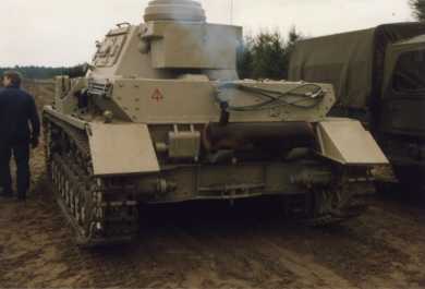
After the war, The Tank Museum, RAC Bovington, put it on display where it remained until December, 1960. At this time General-Major Jolly, commander of the 5th British Armoured Division, presented it to General of Combat Troops, General-Major Munzel, in Munster. Having received a new paint scheme and new number, "R01", it remained on display there until 1980 when it was moved to the Kampftruppenschule 2 (workshop number 1) for restoration. Work proceeded until 1983 and included yet another new paint scheme, this time featuring turret number "413". After this it was moved to the Trier depot and then back to Munster where it is maintained in running order, as indicated by this photo taken in 1988 by Oliver Nephuth.PGT1-p56
|
|
|
|
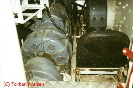
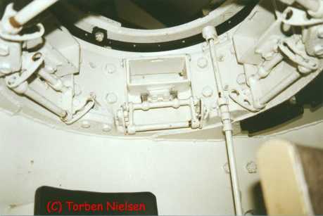
Picture 2
This picture shows the back of the turret and the inside of the commander's cupola. The dark object at the bottom of the photo is the commander's cushioned headrest.
Three of the five observation ports can be seen around the inside of the cupola. The bottom-most horizontal bar acts as a handle to open and close the armored shutters located outside. Thick laminated glass blocks were normally installed in each port, but these are all missing from this example. Tall rectangular cushions were mounted between each port, but these are also missing. This is the mid-production cupola found in Ausf. E through early Ausf. G versions.
The vertical shaft transfers rotation from the turret ring up to the commander's azimuth indicator. This indicator consists of a toothed ring marked off into 12 "clock" positions. These positions correspond with the 12 positions of the left dial of the gunner's azimuth indicator. By using these synchronized indicators, the commander and gunner could communicate direction relative to the facing of the hull no matter what direction the turret was facing. One of the driveshaft's two universal joints can be seen just under the bottom edge of the cupola.
|
Picture 3
Here we're looking forward from behind the radio operator's seat. The treadplate at the bottom of the picture is the front edge of the fighting compartment's floor. This is not the original floor as the tread pattern is different.
At the left we see the Syncron ZF SSG 76 transmission. One of the radio racks is visible above the transmission and the right brake housing can be seen in the photo above the seat back.
The seat itself is not original. Completely unlike the driver's seat, the radio operator's had a round (looking down) seat and a small backrest that folded up out of the way to provide an exit to the fighting compartment.
|
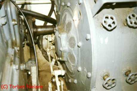
Picture 4
This picture features a close-up of the right steering brake. The transmission is on the left.
|
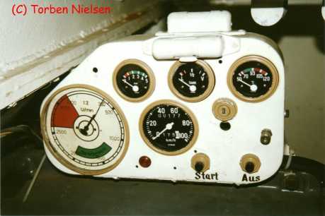
Picture 5
In this photo you're sitting in the driver's seat looking to your right at his control panel. Unfortunately, this is not the original control panel. The picture is of some value, though, in showing a close-up of the tank's interior lights, two of which have been mounted on the substitute control panel. These no longer function and have long since been painted over (the recessed area was the glass of the bulb).
|
|
Previous Page |
Next Page
|
|